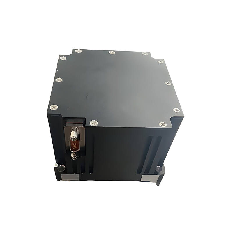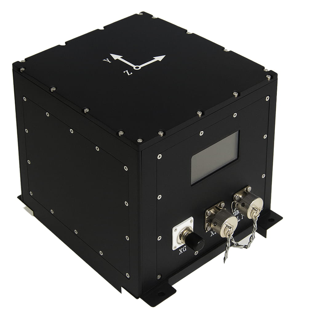
Sensor inercial MEMS IMU U3700 à prova d'água de alta precisão com protocolos Canopen Modbus.
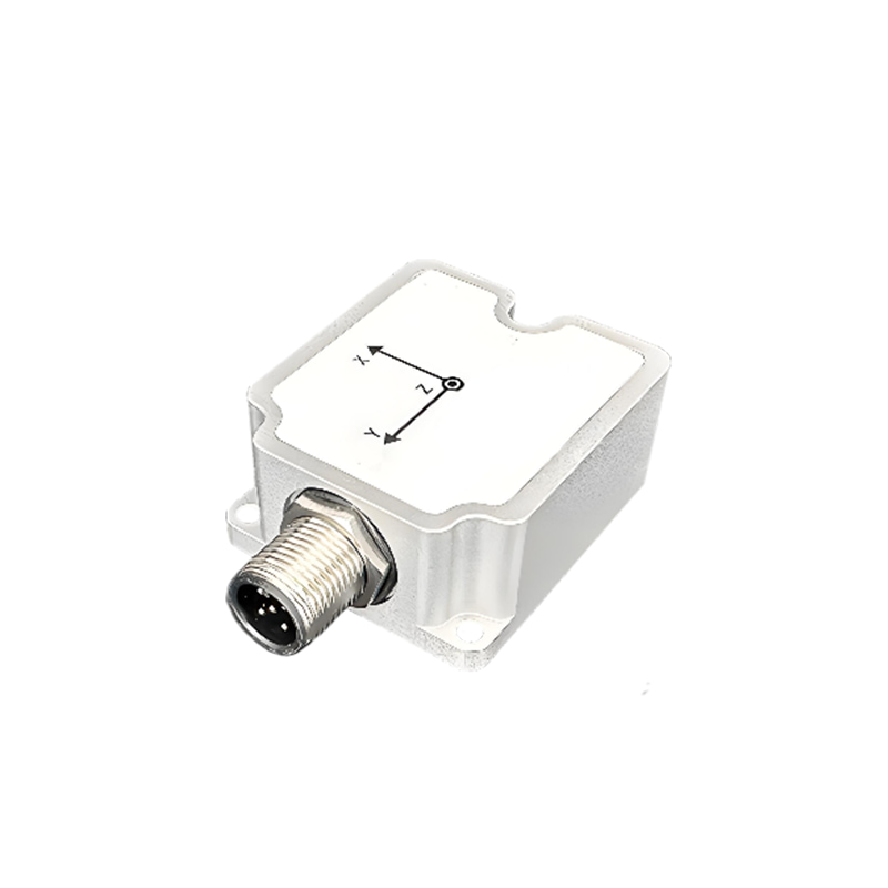
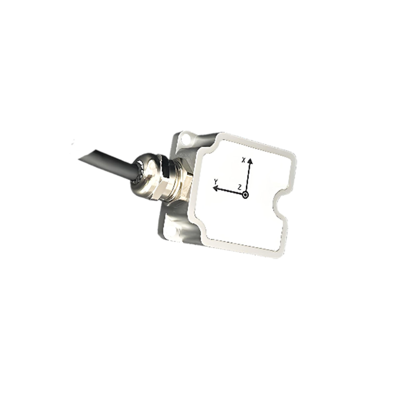
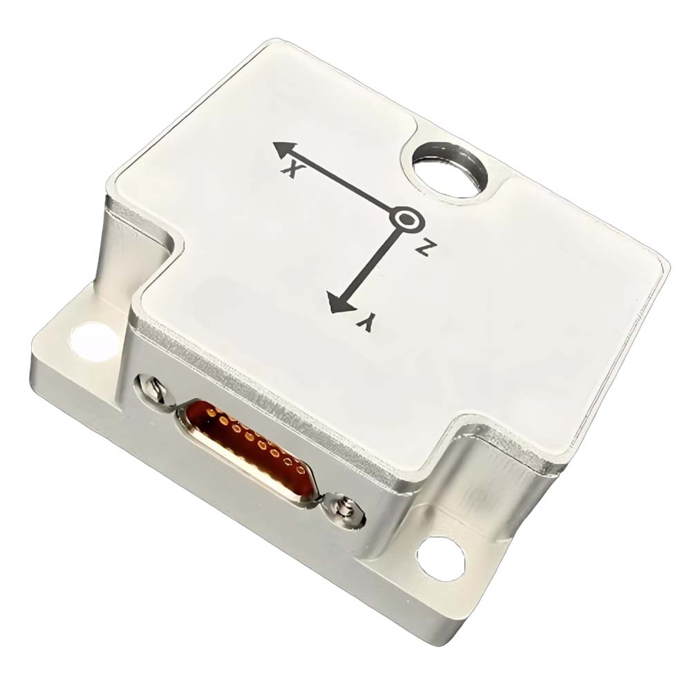
A série U3700 é um sensor IMU/VRU/AHRS composto por uma matriz de MEMS-IMU e um magnetômetro. Equipado com filtragem de Kalman estendida adaptativa desenvolvida internamente, algoritmo de análise dinâmica de ruído da IMU e algoritmo de análise do estado de movimento do portador, ele garante a precisão do ângulo de atitude em condições de alta dinâmica e reduz a deriva do ângulo de direção.
Antes de sair da fábrica, cada sensor passa por uma compensação precisa, incluindo temperatura, viés zero, fator de escala e eixo transversal.
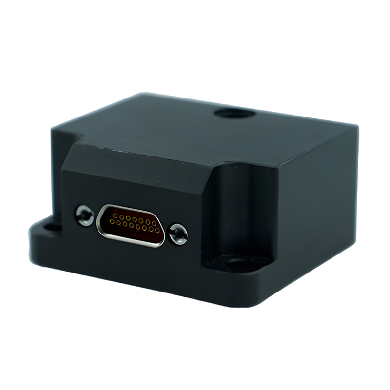
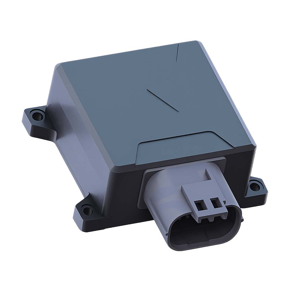
Os sensores da série U3700 transmitem dados através de diversas interfaces, como UART (RS-232/TTL), RS-485 e CAN, e oferecem amplas opções de configuração pelo usuário. A série U3700 pode sincronizar com o sistema através de acionamento externo e também alinhar-se com sistemas externos, como radares e câmeras, por meio da função de saída síncrona. A interface gráfica multifuncional (GUI) permite uma avaliação rápida dos produtos, incluindo, entre outras funcionalidades, configuração de módulos, visualização de dados, atualização de firmware e registro de dados.
Número da peça, :
U3700Pedido (MOQ) :
1Séries e parâmetros do produto
| Precisão de Atitude | U3700-A | U3700-B | U3700-C | U3700-D | U3700-E | U3700-F | U3700-G | Unidade |
| Inclinação (±90°) / Rotação (±180°) (estático) | 0,15 (nominal), 0,2 (máximo) | ° | ||||||
| Inclinação (±90°) / Rotação (±180°) (dinâmica) | 0,15 (nominal) 0,3 (máximo) | 0,15(nom) 0,2 (máx.) |
° | |||||
| Deriva estática de guinada (±180°) 2 horas (6 graus de liberdade) ① | 0,15 (nominal), 0,2 (máximo) | ° | ||||||
| Deriva dinâmica de guinada (±180°) (6 graus de liberdade) ② | 9 | 5 | ° | |||||
| Assistência magnética (AHRS)③ | 2(nominal), 3(máximo) | ° | ||||||
| Erro de rotação de guinada (6DOF) (rotação inferior a 100°/s)④ | <0,8(nom) 3 (máx.) |
<0,8(nom) 1 (máx.) |
<0,8(nom) 1,3 (máx.) |
° | ||||
| Observação: ① Módulo estacionário horizontal por 2 horas. ② O módulo foi medido após 1 hora de movimento em um robô de interior, 1σ ③ Após a calibração geomagnética, o produto precisa ser configurado no modo AHRS quando não houver interferência do campo magnético na área circundante. ④ A plataforma giratória gira continuamente por 10 voltas, e o ângulo de direção acumula erro. |
||||||||
| Giroscópio | U3700-A | U3700-B | U3700-C | U3700-D | U3700-E | U3700-F | U3700-G | Unidade |
| Faixa de medição | ±2000 | ±4000 | °/s | |||||
| Resolução | 16 | 20 | pedaço | |||||
| Fator de escala (100°/s)① | <500(nom) 600 (máx.) |
<200(nom) 350 (máx.) |
<100(nom) 200 (máx.) |
ppm | ||||
| Não linearidade② | ±0,05 | %Fs | ||||||
| Densidade de ruído③ | 0,015 | 0,008 | 0,006 | 0,0025 | 0,0015 | °/s/√Hz | ||
| Largura de banda de 3dB | 90 (nominal), 200 (máximo) | 90 (nominal), 400 (máximo) | Hz | |||||
| Saída em velocidade zero④ | ±0,1 | °/s | ||||||
| Taxa de amostragem | 1000 | Hz | ||||||
| Instabilidade de polarização zero (Allan, 1σ) | 3 | 1.6 | 1.2 | 1.7 | 1 | °/h | ||
| Estabilidade de polarização zero (10s, 1σ) | 10 | 5 | 4 | 2.3 | °/h | |||
| Repetibilidade de viés zero (1σ) | 15 | 12 | 8 | 3.7 | 1.8 | °/h | ||
| Caminhada aleatória angular (Allan 1σ) | 0,42 | 0,25 | 0,18 | 0,15 | 0,05 | °/√h | ||
| Polarização zero em temperatura total -40-85℃⑤ | 0,07 (nominal), 0,2 (máximo) | °/s | ||||||
| Sensibilidade do acelerômetro (todos os 3 eixos) | 0,1 | 0,05 | °/s/g | |||||
| Notas: ①: Gire a plataforma giratória 10 vezes em ambas as direções e faça a medição média. ②: Desvio máximo da linha de melhor ajuste dentro do intervalo especificado ③: Teste a média da amostra ④: Após a calibração inicial de viés zero, o viés zero pode ser estimado em tempo real no mecanismo do algoritmo. ⑤: A taxa de aumento de temperatura medida pela plataforma giratória da câmara de temperatura no laboratório é inferior a 3℃/min. |
||||||||
| Acelerômetro | U3700-A | U3700-B | U3700-C | U3700-D | U3700-E | U3700-F | U3700-G | Unidade |
| Faixa de medição | ±12 | ±8(nom), ±32(máx) | g | |||||
| Resolução | 16 | 20 | pedaço | |||||
| Desvio inicial de polarização | 5 (máx.) | 2(nominal), 5(máximo) | mg | |||||
| Não-linearidade | 0,5 | 0,01 | %Fs | |||||
| Largura de banda de 3dB | 80 (nominal), 200 (máximo) | 80 (nominal), 400 (máximo) | Hz | |||||
| Taxa de amostragem | 1600 | 1000 | Hz | |||||
| Instabilidade de polarização zero (Allan, 1σ) | 0,03 | 0,018 | 0,014 | 0,012 | 0,007 | mg | ||
| Estabilidade de polarização zero (10s, 1σ) | 0,07 | 0,035 | 0,025 | 0,015 | 0,008 | mg | ||
| Repetibilidade de viés zero (1σ) | 0,34 | 0,15 | 0,1 | 0,11 | 0,05 | mg | ||
| Caminhada aleatória angular (Allan, 1σ) | 0,08 | 0,04 | 0,028 | 0,018 | 0,01 | m/s/√h | ||
| Polarização zero em temperatura total -40-85℃ (1σ) | 2(nominal), 3(máximo) | 2,5 (nominal), 5 (máximo) | mg | |||||
| Magnetômetro | U3700-A | U3700-B | U3700-C | U3700-D | U3700-E | U3700-F | U3700-G | Unidade |
| Faixa | / | / | ±8 | ±8 | / | ±20 | / | Gauss |
| Resolução (Fs=2G) | / | / | 2 | 2 | / | 2 | / | mGuass |
| Amostragem | / | / | 200 | 200 | / | 200 | / | Hz |
| Linearidade (linha reta de melhor ajuste Fs=2G) | / | / | 0,1 | 0,1 | 0,2 | Fs% | ||
| Sensor de temperatura | U3700-A | U3700-B | U3700-C | U3700-D | U3700-E | U3700-F | U3700-G | Unidade |
| Faixa | -40 ~ +85 | ℃ | ||||||
| Erro de deslocamento | ±1 | K | ||||||
| Mecânica/Ambiental | U3700-A | U3700-B | U3700-C | U3700-D | U3700-E | U3700-F | U3700-G | Unidade |
| Fonte de energia | 4.8 ~ 48 (USB/UART(RS-232/TTL)) 7 ~ 48 (RS485/CAN) |
V | ||||||
| Consumo de energia | 300 | 400 | 600 | 400 | 600 | mW | ||
| Temperatura de trabalho | -40 - 85 | ℃ | ||||||
| Horário de início① | 2 | s | ||||||
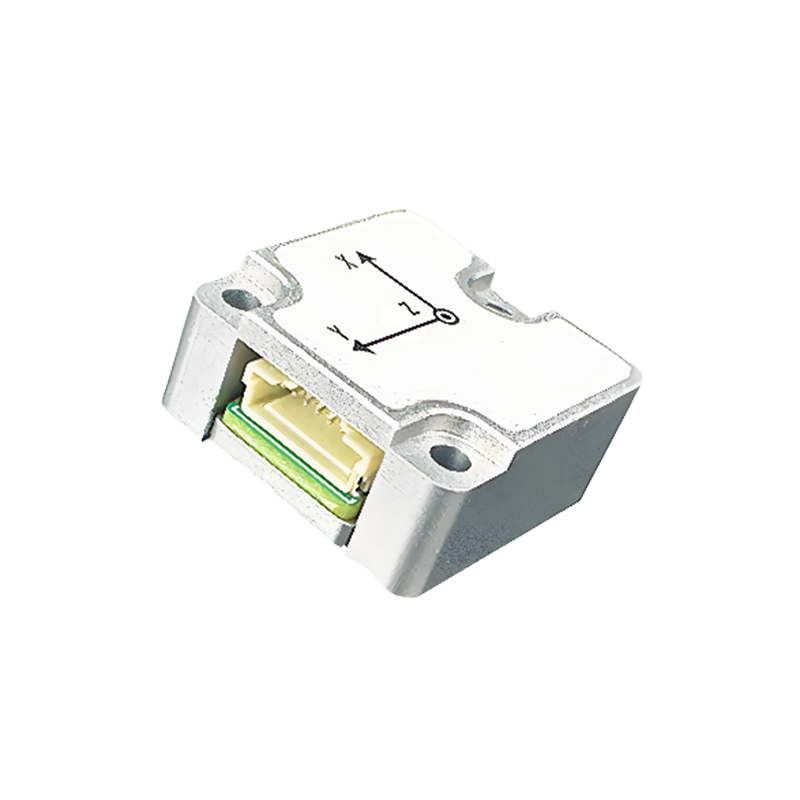
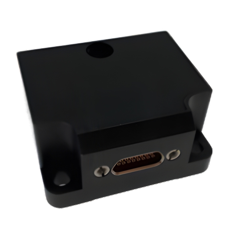
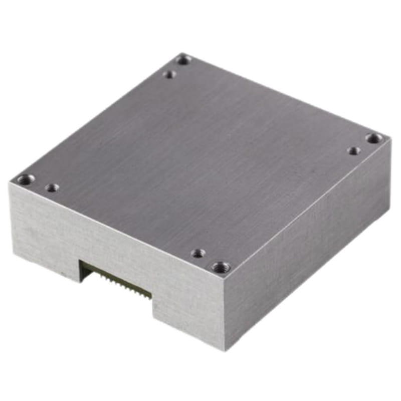
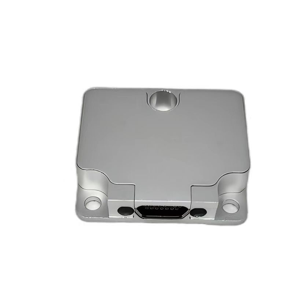
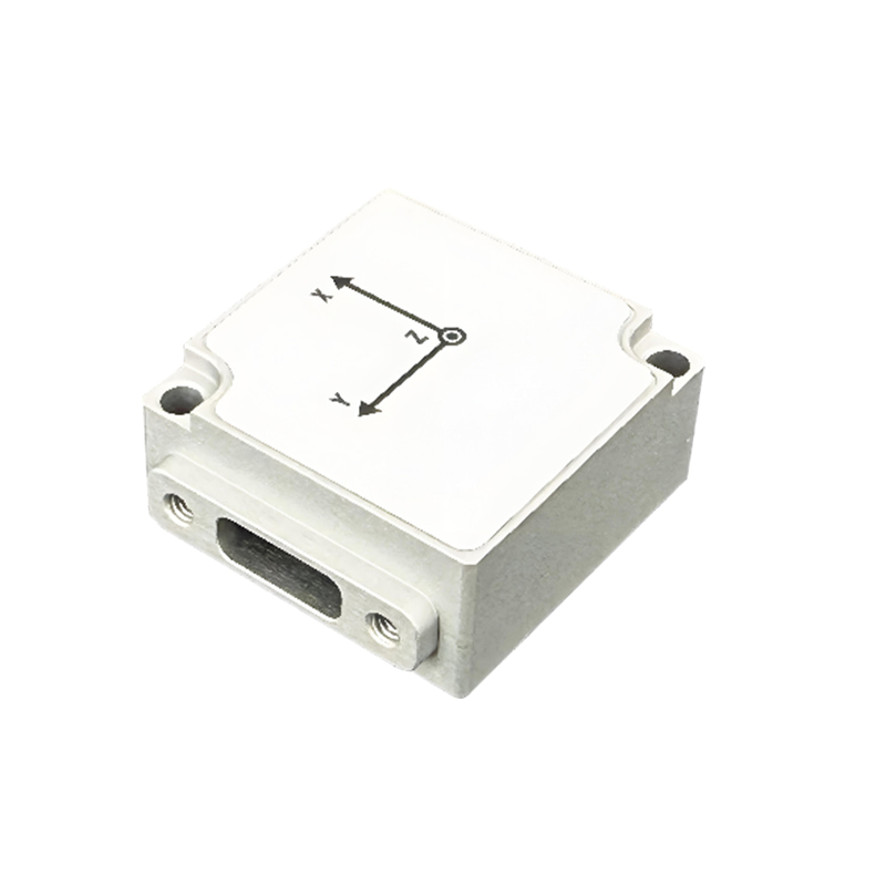
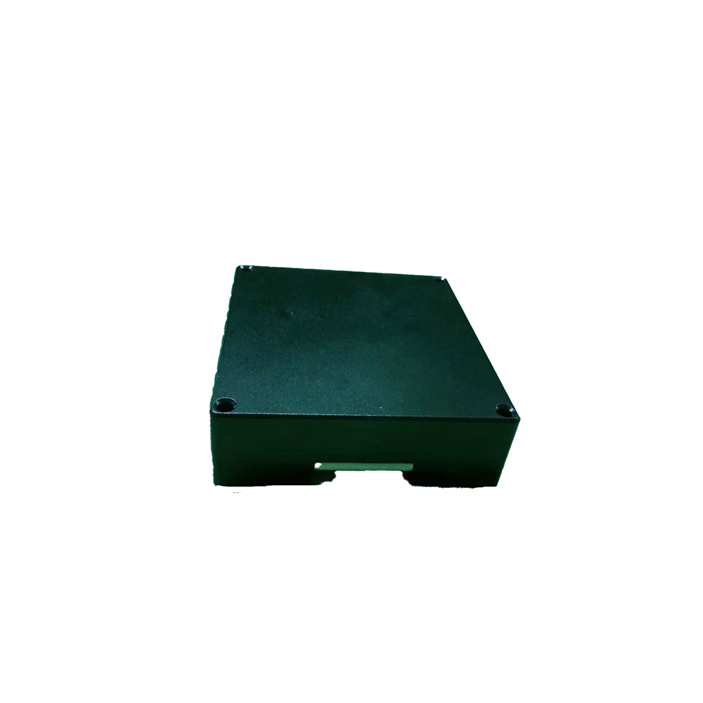
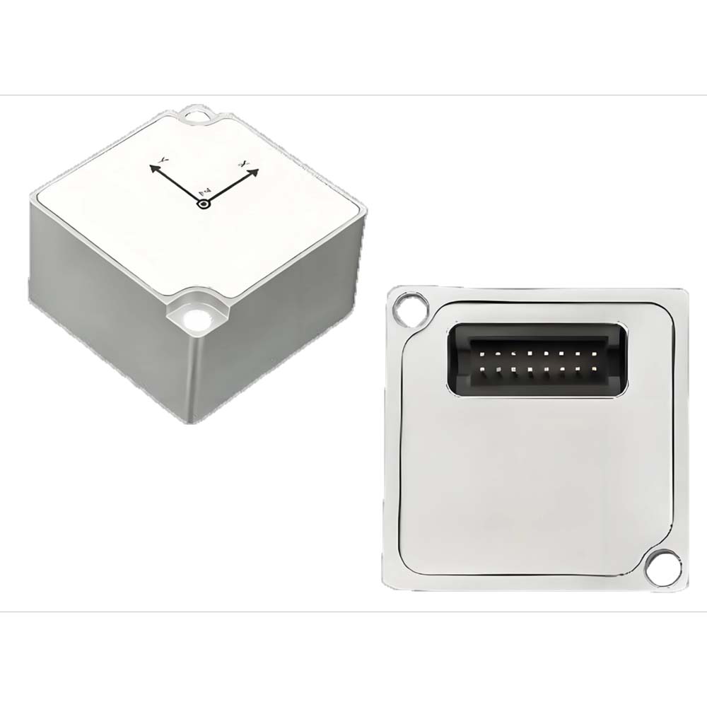
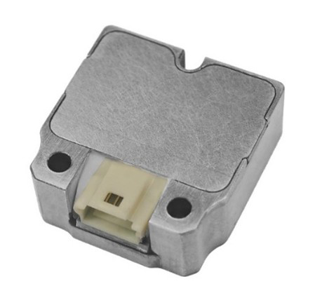
| Tamanho | Interface do conector M12: 58,5*40*20 Interface do conector PG: 40*36*16 |
mm | ||||||
| Peso | <75 | g | ||||||
| Material e processo da casca | Liga de alumínio CNC | |||||||
| Parafusos de montagem | M3 | |||||||
| Antivibração | 1,0 mm (10 Hz - 58 Hz) e ≤ 20 g (58 Hz - 600 Hz) | |||||||
| Choque (duração) <1ms) | 2000 | g | ||||||
| Proteção ambiental | Diretiva RoHS 2011/65/UE | |||||||
| EMC | CE | |||||||
| Grau IP | IP68 Resistente à água | |||||||
| Teste de queda | Queda livre 3 vezes em uma plataforma experimental de 75 cm de altura | |||||||
| Choque térmico | Aumente a temperatura de -40 °C para 85 °C em 1 hora, 5 vezes. | |||||||
| Notas: ① O tempo de inicialização refere-se ao tempo necessário para o sistema ser desligado e gerar dados válidos. Durante esse período, o módulo deve permanecer imóvel. |
||||||||
| Interface | Parâmetros | Doença | Min | Normal | Máximo | Unidade |
| UART | Taxa de transmissão① | 9600 | 115200 | 921600 | bps | |
| Peças iniciais | 1 | pedaço | ||||
| Comprimento dos dados | 8 | pedaços | ||||
| Pare um pouco | 1 | pedaço | ||||
| Soma de verificação | Nenhum | pedaço | ||||
| Taxa de quadros de saída② | 0 | 100 | 1000 | Hz | ||
| Impedância de entrada | RS-232 | 3 | 5 | 7 | kΩ | |
| Impedância de saída | 300 | 10M | Ω | |||
| PODE | Taxa de transmissão③ | 125 | 500 | 1000 | kbps | |
| Taxa de quadros de saída④ | 5 | 100 | 200 | Hz | ||
| Impedância de entrada⑤ | com resistor de 120 Ω | 120 | Ω | |||
| sem resistor de 120 Ω | 19 | 30 | 52 | kΩ | ||
| RS485 | Taxa de transmissão | Modbus | 921600 | 115200 | 115200 | bps |
| não-Modbus | 921600 | 115200 | 460800 | bps | ||
| Peças iniciais | 1 | pedaço | ||||
| Comprimento dos dados | 8 | pedaços | ||||
| Pare um pouco | 1 | pedaço | ||||
| Soma de verificação | Nenhum | pedaço | ||||
| Taxa de quadros de saída | Modbus | 0 | 10 | 50 | Hz | |
| não-Modbus | 0 | 100 | 250 | Hz | ||
| Impedância de entrada⑤ | com resistor de 120 Ω | 120 | Ω | |||
| sem resistor de 120 Ω | 48 | kΩ | ||||
| Pino de disparo | Tensão lógica⑥ | Alto | 2 | V | ||
| Baixo | 0,6 | V | ||||
| Atraso⑥ | Do gatilho à transmissão de dados | 800 | us | |||
| Notas: ① Caso sejam necessárias modificações, consulte o manual de instruções e programação. ② O sensor suporta saída de dados em 1, 5, 10, 50, 200, 250, 500 e 1000 Hz. ③ Caso sejam necessárias modificações, consulte o manual de instruções e programação. ④ O sensor suporta saída de dados de 5, 10, 50, 100 e 200 Hz. ⑤ Por padrão, não há nenhum resistor de 120 Ω conectado. ⑥ Consulte o capítulo sobre a função de sincronização e o manual de instruções e programação para obter informações sobre o acionamento e a configuração. |
||||||
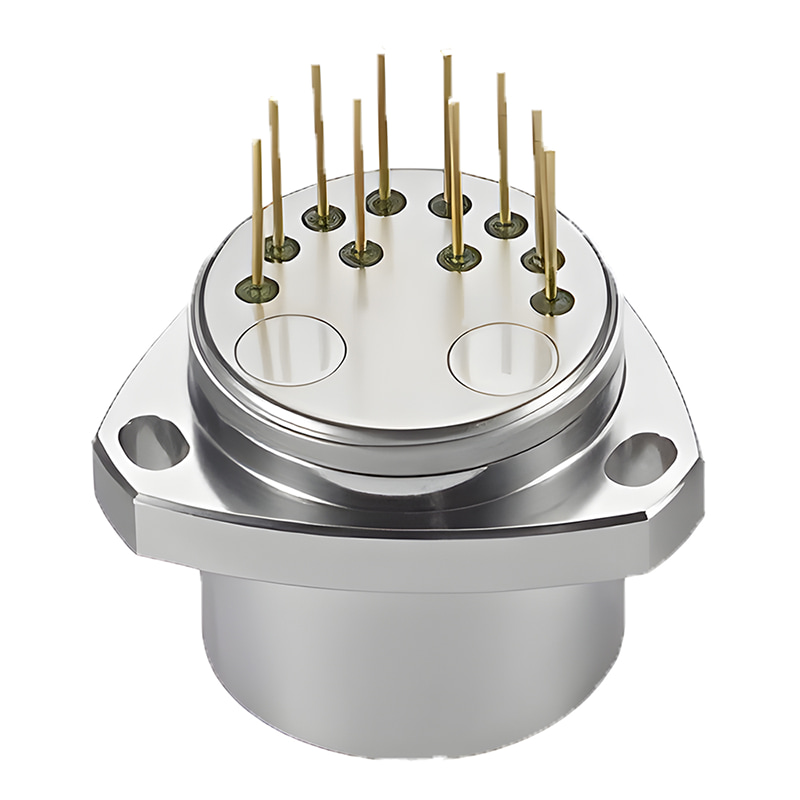
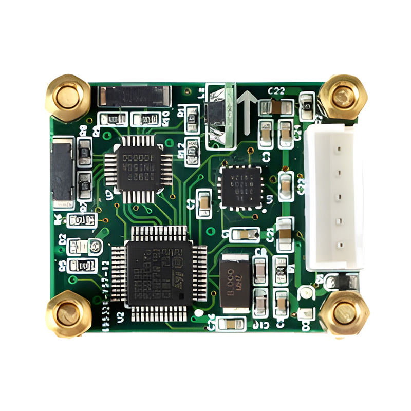
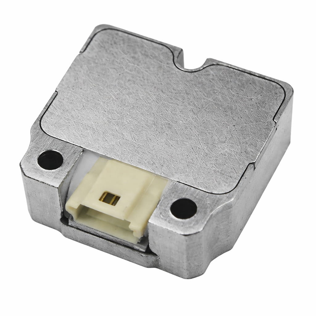
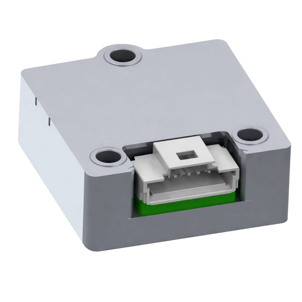
Processo de produção
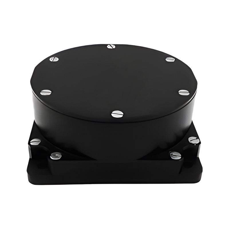
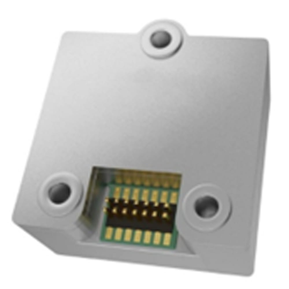
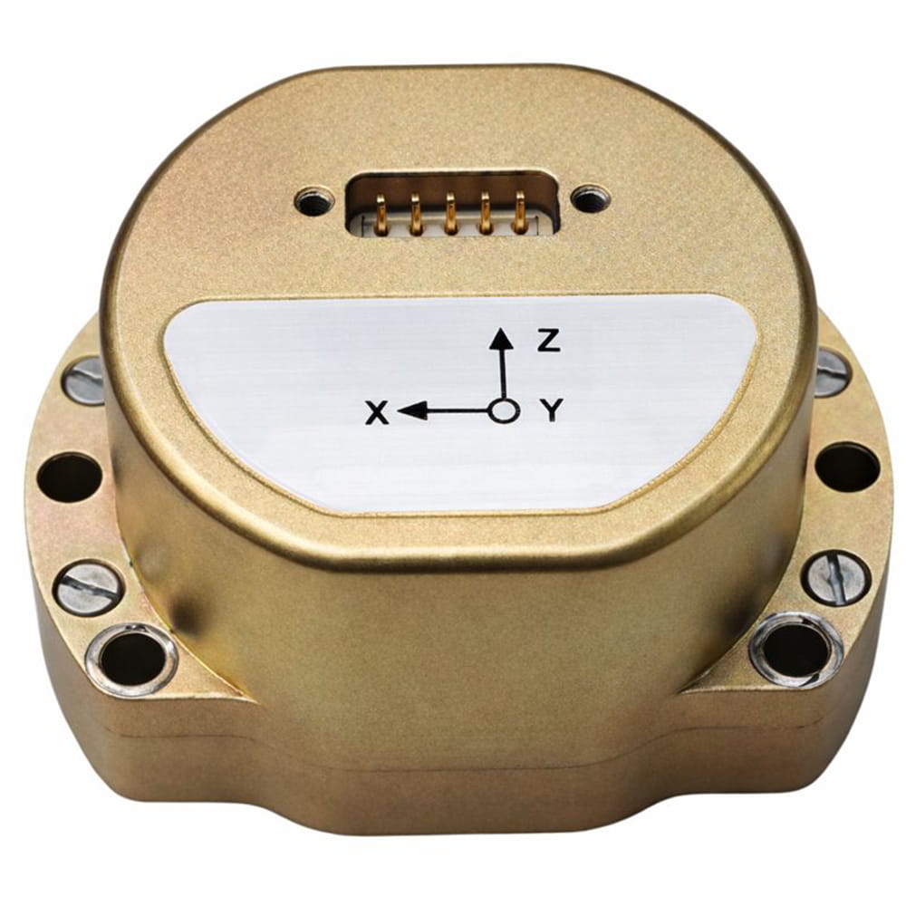
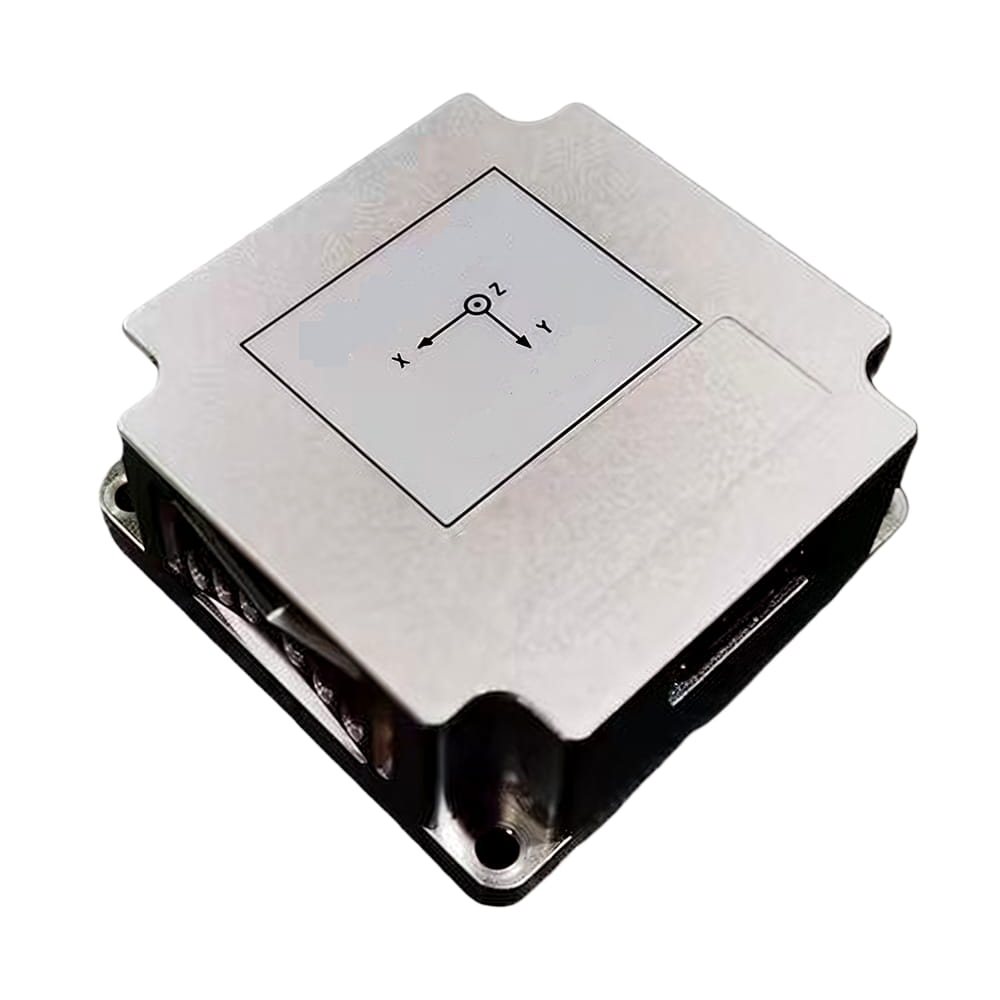
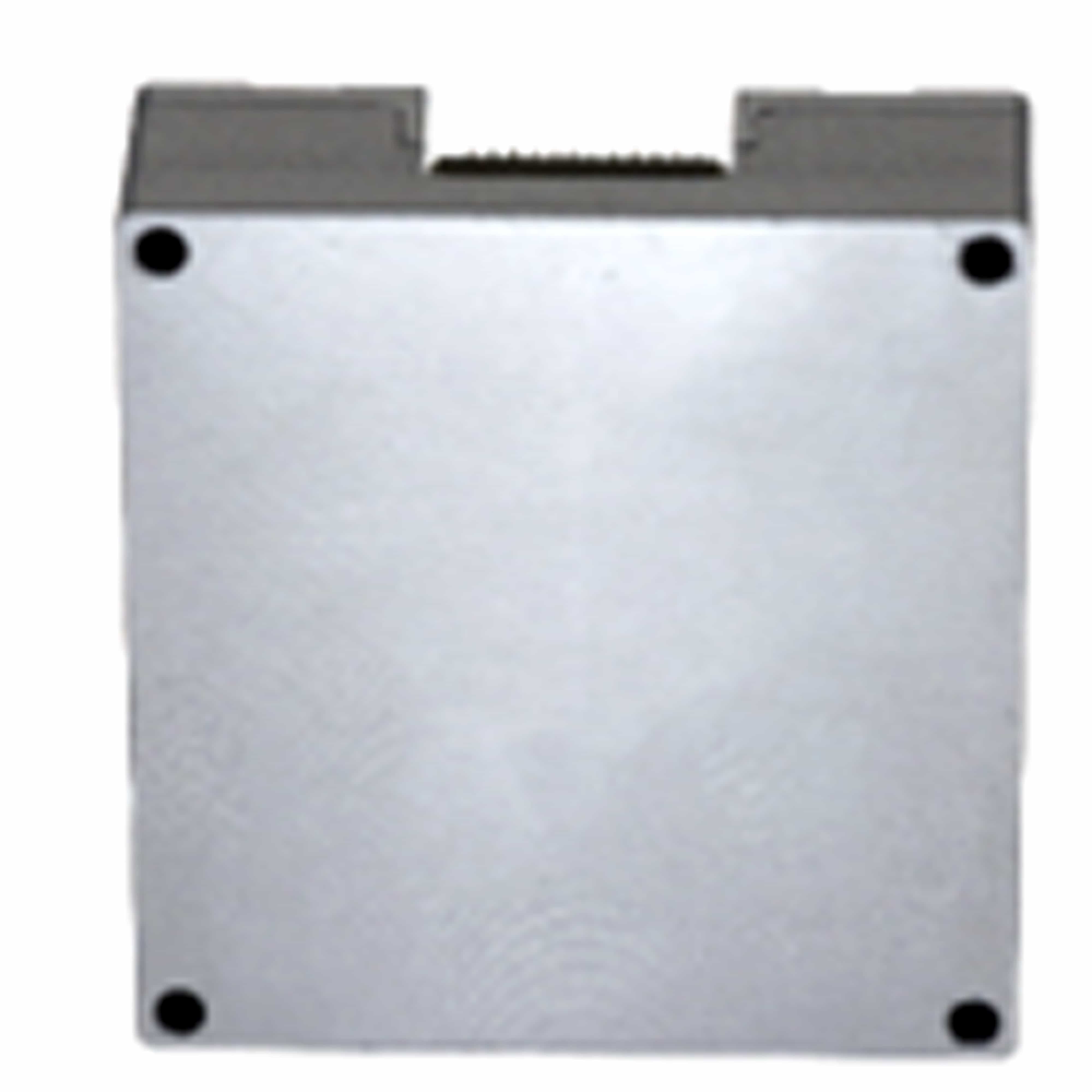
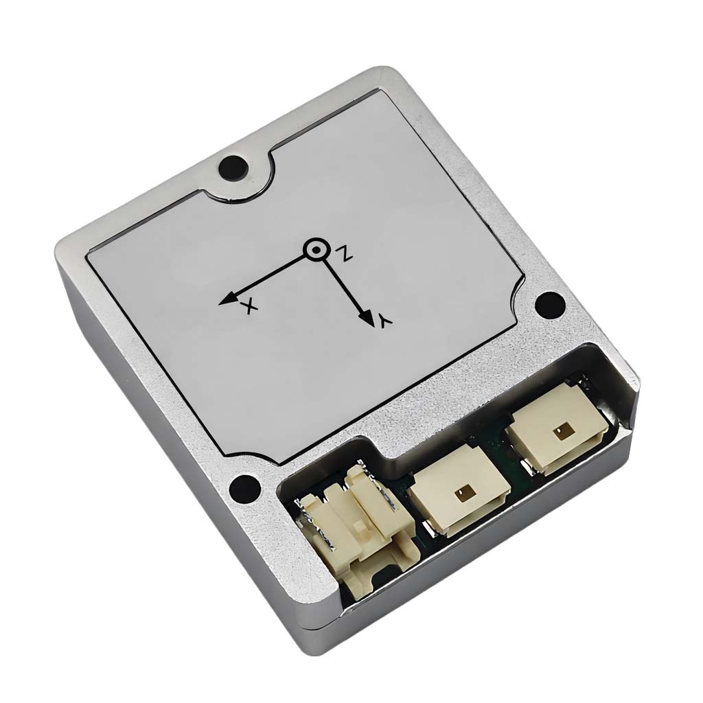
Dimensões do produto

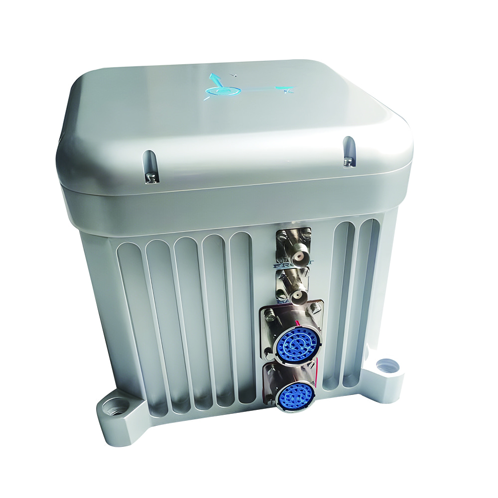
Cenários de aplicação


Perguntas frequentes

Xml política de Privacidade blog Mapa do site
Direitos autorais @ Micro-Magic Inc Todos os direitos reservados.
 REDE SUPORTADA


 Português