Análise de erros e soluções para medições de inclinação de alta precisão
No projeto de sistemas de medição de inclinação de alta precisão, o controle de erros é fundamental para determinar o desempenho do sistema. Este artigo combina resultados de pesquisas existentes e prática de engenharia para discutir métodos de implementação, fontes de erro, métodos de análise e soluções sob quatro aspectos, fornecendo subsídios para o projeto e otimização de sistemas de medição de inclinação de alta precisão.
⚪Vibração mecânica: Quando os sensores são instalados em um ambiente vibratório, a vibração pode causar flutuações no sinal de saída, como em plataformas de veículos ou cenários de equipamentos industriais, onde a vibração pode introduzir um desvio de medição de ±0,5°.
⚪ Deriva térmica: As mudanças de temperatura causam deriva do zero do sensor, especialmente quando a temperatura de operação excede a faixa de calibração (como -20℃~65 ℃), o erro pode chegar a 0,002°/℃.
⚪ Interferência eletromagnética: Flutuações de energia ou campos eletromagnéticos externos podem interferir na cadeia de sinal do sensor, afetando a precisão da conversão analógico-digital.
⚪ Erro não linear: A saída dos sensores de inclinação MEMS apresenta uma relação não linear com o ângulo de inclinação; por vezes, os erros não lineares podem atingir um desvio de 0,1° dentro de uma faixa de ± 30°.
⚪ Limitações de ruído e resolução: O processamento inadequado de sinais analógicos pode levar a uma diminuição da resolução efetiva, como por exemplo, um número insuficiente de bits no conversor analógico-digital (ADC) que pode não ser capaz de detectar pequenos sinais no nível de 0,175 mV.
⚪ Erro de instalação: Uma base irregular ou mal fixada faz com que o plano de referência do sensor não seja paralelo à superfície medida, resultando em desvio sistemático.
Se houver aceleração externa (como vibração ou movimento) no dispositivo, a saída do acelerômetro conterá componentes de aceleração dinâmica, resultando em erros no cálculo do ângulo de inclinação. Nesse caso, é necessário combinar os dados de um giroscópio ou magnetômetro para fusão (como a filtragem de Kalman).
um) Projeto de redução de vibração: Utilize almofadas de borracha para isolar a fonte de vibração ou selecione sensores com função de filtragem dinâmica.
b) Compensação de temperatura:
⚪Nível de hardware: Selecione chips MEMS com sensores de temperatura integrados para corrigir a deriva por meio da aquisição de temperatura em tempo real.
⚪ Nível de software: Estabelecer uma equação de ajuste da curva de erro de temperatura, como por exemplo, utilizando um algoritmo de compensação polinomial para reduzir a precisão da deriva de temperatura para 0,002 °C a -20~65 °C.
c) Alimentação e isolamento de sinal: Fontes de referência de alta estabilidade (como o LM236) são usadas para alimentar o sensor, e circuitos de desacoplamento são projetados para reduzir o impacto da ondulação da energia.
um) Projeto de cadeia de sinal de alta precisão:
⚪ Utilize amplificadores operacionais de baixo ruído (como o ICL7653) e circuitos de conversão diferencial (como o AD8138AR) para melhorar a taxa de rejeição de modo comum e a relação sinal-ruído.
⚪ Utilizando um ADC do tipo ∑-Δ de 24 bits (como o ADC integrado no C8051F350), combinado com um filtro SINC3 para reduzir o ruído e obter uma resolução efetiva de 20 bits.
b) Correção não linear: Ao subdividir o intervalo de medição e ajustá-lo com curvas senoidais segmentadas, o erro não linear é reduzido de 0,11° para 0,0044°.
um) Método de mapeamento com sensor duplo: Ao trabalhar em conjunto com o primeiro sensor de inclinação (referência de calibração) e o segundo sensor (a ser calibrado) na plataforma de instalação, estabelece-se uma relação de mapeamento linear entre o ângulo de deslocamento e o ângulo de medição para corrigir desvios mecânicos de instalação.
b) Calibração horizontal: Utilize um nível de alta precisão para calibrar a superfície de instalação, garantindo que o plano de referência do sensor esteja paralelo à superfície medida, e fixe a base com parafusos de torque.
um) Fusão multissensor: integração de acelerômetros e giroscópios de três eixos, previsão de ângulos de inclinação dinâmicos por meio de filtragem de Kalman ou algoritmos LSTM e aumento das taxas de atualização para mais de 100 Hz.
b) Otimização do modelo de catenária: Com base na deformação dinâmica do fio, a equação da catenária é usada para ajustar o limite de segurança em tempo real, em combinação com parâmetros ambientais (velocidade do vento, temperatura), reduzindo a taxa de erros de avaliação para menos de 0,3%.
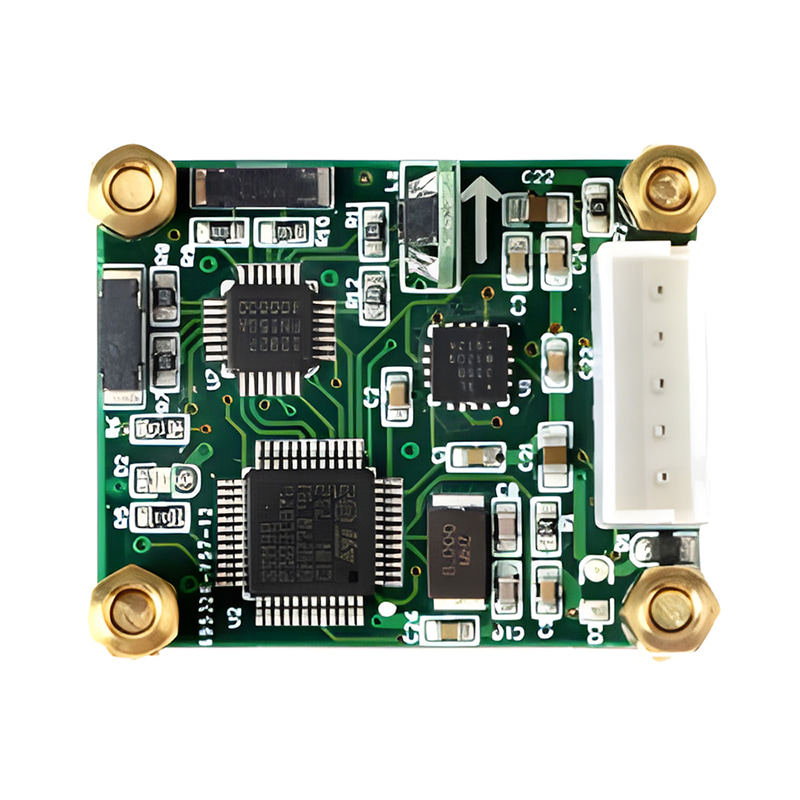
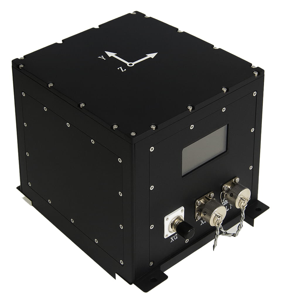
O sistema de medição de inclinação baseado em SOC (série T7000-H) atinge um erro absoluto máximo de 0,005° e um erro relativo de <0,02% através de compensação de temperatura e ajuste de curvas, e tem sido aplicado em exploração geológica e monitoramento de pontes.
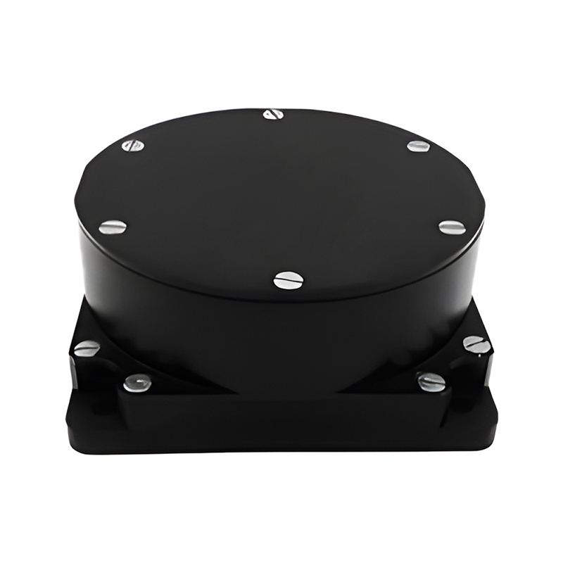
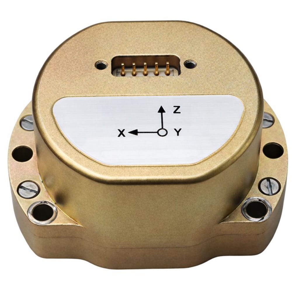
O sensor de inclinação da série T70-B foi projetado para a medição de produtos químicos perigosos em ambientes à prova de explosão. O microcontrolador interno, o módulo de inclinação MEMS, o circuito de alimentação e o circuito de saída foram otimizados por meio de um projeto de proteção para garantir o desempenho ideal em condições extremas de trabalho e ambientes de medição de longa duração. A precisão da medição pode atingir 0,01°.
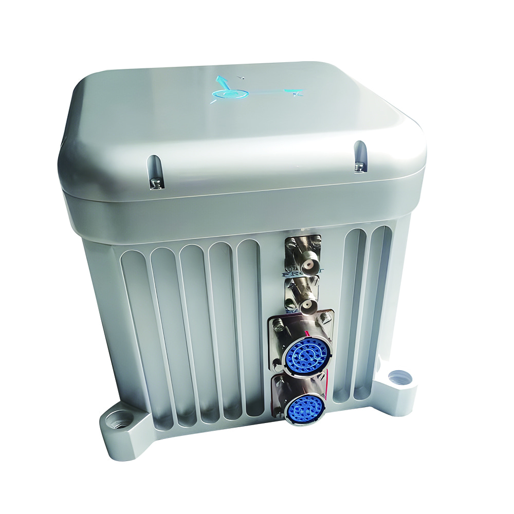
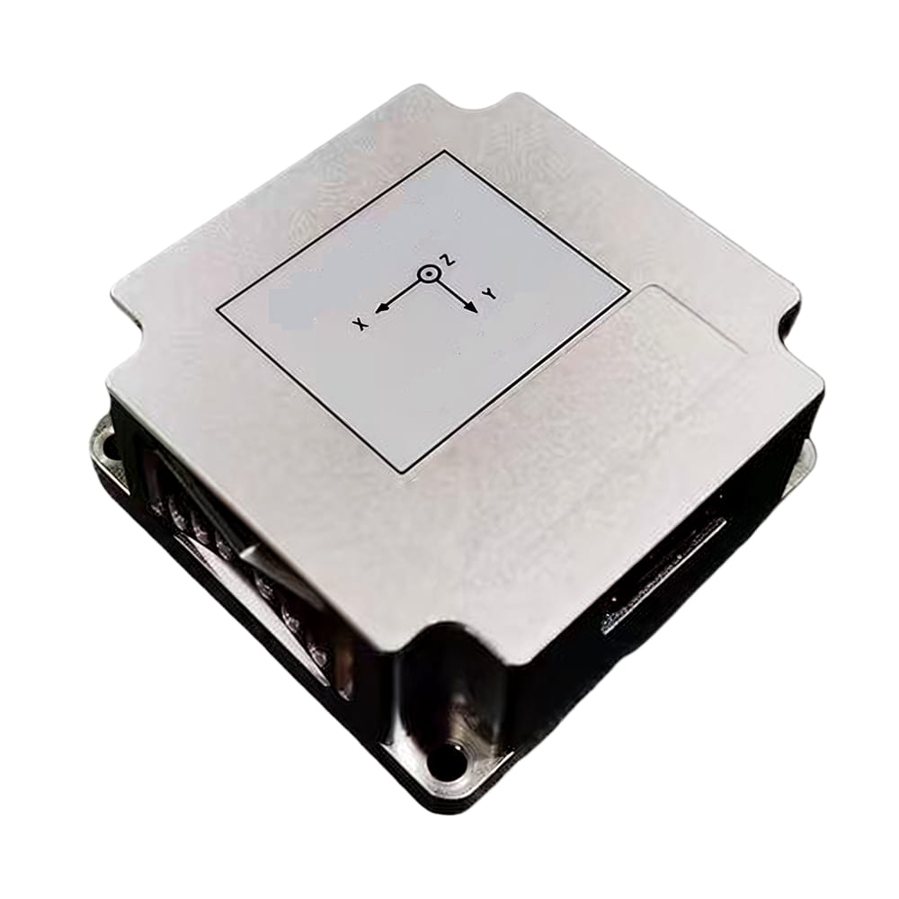
O sensor de inclinação sem fio T7000-I foi projetado para aplicações industriais onde os usuários não dispõem de fonte de alimentação ou necessitam de medição dinâmica em tempo real da postura e do ângulo de objetos. Alimentado por baterias de lítio e baseado em tecnologias de IoT, como Bluetooth e Zigbee (opcional), com design de nível industrial, apresenta boa estabilidade a longo prazo e baixa deriva de zero. Ele pode entrar automaticamente em modo de baixo consumo de energia, eliminando assim a dependência do ambiente de uso.
1) Compensação inteligente: Utilização de algoritmos de IA (como redes neurais) para corrigir de forma adaptativa erros de múltiplas fontes e reduzir a dependência da calibração manual.
2) Design integrado: Integração de sensores, condicionamento de sinal e unidades de processamento em um único chip para reduzir custos e melhorar a confiabilidade.
3) Análise de acoplamento de campos multifísicos: Combinação de modelos de mecânica, termodinâmica e eletromagnetismo para alcançar a previsão completa do erro de condição.
Por meio do caminho tecnológico acima descrito, espera-se que os sistemas de medição de inclinação de alta precisão alcancem aplicações mais amplas em áreas como aeroespacial, equipamentos inteligentes e monitoramento de infraestrutura.

Xml política de Privacidade blog Mapa do site
Direitos autorais @ Micro-Magic Inc Todos os direitos reservados.
 REDE SUPORTADA


 Português