Informações gerais de suporte
Para a instalação e utilização, os utilizadores devem escolher um ambiente com o mínimo de interferência magnética. Procurem posicionar o produto o mais longe possível de ferro, níquel, ímanes, motores e outras substâncias magnéticas. Caso existam estes materiais magnéticos por perto, mantenham uma distância mínima de 0,5 m. Para garantir o desempenho ideal de medição do produto, devem ser utilizadas chaves de fendas não magnéticas e parafusos não ferrosos durante a instalação. É imprescindível evitar que substâncias com forte magnetismo, como ímanes e motores, se aproximem a menos de 10 cm da bússola, uma vez que isso pode causar uma diminuição irreversível na precisão da medição.
A calibração dos indicadores de desempenho da IMU, como viés zero, fator de escala, erro de desalinhamento e compensação de temperatura, foi realizada principalmente. A faixa de compensação de temperatura corresponde à faixa de temperatura operacional do giroscópio e do acelerômetro, e varia de acordo com o produto.
Para garantir a estabilidade e a confiabilidade do desempenho do sensor, são realizados testes de repetibilidade com viés zero para assegurar a consistência no desempenho do produto. Além disso, são conduzidos testes em altas e baixas temperaturas, vibração e outras condições ambientais para garantir a confiabilidade do produto.
Sim, todas as IMUs passam por compensação de temperatura antes de saírem da fábrica. A faixa de compensação de temperatura corresponde à faixa de temperatura operacional do giroscópio e do acelerômetro, e varia de acordo com o produto.
O erro na navegação inercial provém principalmente dos defeitos inerentes aos sensores inerciais, que aumentam de forma quadrática (posição) ou linear (atitude) ao longo do tempo.
Os principais motivos para o acúmulo de erros ao longo do tempo são: deriva do giroscópio, viés do acelerômetro; a integração do erro de viés do acelerômetro pode levar a um erro de velocidade, e a integração secundária pode causar deriva de posição (por exemplo, um viés de 1 mg durante 1 hora pode resultar em um erro de posição de cerca de 60 metros); sensibilidade à temperatura; erro de instalação; o sistema de coordenadas do sensor não está estritamente alinhado com o sistema de coordenadas do veículo.
Os métodos comuns para lidar com o acúmulo de erros incluem:
Não, a IMU não possui um modelo de compensação de envelhecimento.
Normalmente, fixamos a IMU MEMS à plataforma giratória, e o acelerômetro coleta dados usando um método estacionário de 12 posições. O giroscópio coleta dados girando para frente e para trás em velocidades específicas (como 30). °/s, 60 °/s, etc.), e utiliza algoritmos de otimização para obter o viés zero, o fator de escala e a matriz de erro de desalinhamento do acelerômetro e do giroscópio.
Atualmente, nosso alinhamento inicial utiliza dois sensores, um acelerômetro e um magnetômetro, para calcular o ângulo de atitude atual (rolagem, inclinação, guinada) como ângulo de alinhamento inicial. Quando o usuário envia a instrução FF 5A 68 00 00 F0 1C 0D, o produto executa automaticamente a calibração inicial descrita acima e continua a monitorar a atitude do alvo. Nesse momento, o AHRS retorna a instrução FF 5A 68 00 01 00 1D D4 0D, apenas notificando o cliente se a calibração inicial foi realizada com sucesso. Observe que, mesmo com a execução do comando acima, a saída não será zero devido a erros de medição dos sensores.
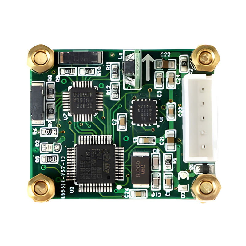
Nosso giroscópio de fibra óptica suporta o protocolo de comunicação serial bidirecional RS422. O transmissor (Tx+, Tx-) é usado para enviar os dados de medição do giroscópio para o lado do cliente, e o receptor (Rx+, Rx-) é usado para receber sinais de disparo externos. Você precisa projetar uma placa de circuito impresso conforme mostrado no diagrama a seguir ou usar um projeto de circuito existente para implementar as funções descritas.

Os dados de saída do giroscópio incluem dados de velocidade angular e temperatura. O valor original dos dados de velocidade angular é um inteiro com sinal de 32 bits, e os dados de temperatura são um inteiro com sinal de 16 bits.
Converter dados de temperatura para valores Celsius:
Considerando que os dados de temperatura recebidos sejam Dt, Te = Dt * 0,0625, a unidade de Te é ℃
Converter dados de velocidade angular em valores de velocidade angular em graus por segundo:
Considerando que os dados de velocidade angular recebidos sejam Dg, o fator de escala do giroscópio fornecido no manual seja Kg e a frequência de amostragem (frequência de comunicação do giroscópio) seja fs.
Velocidade angular W=Dg/(Kg/fs)
A seguir, apresentamos as alterações no fator de escala em diferentes temperaturas em nosso relatório de testes, e suas variações são mínimas em diferentes temperaturas.
Por favor, utilize os valores em 25. ° Temperatura ambiente C: 15143697

Em comparação com os sistemas de navegação integrados GNSS/INS, a navegação puramente inercial (que depende apenas de sensores inerciais e não de sinais externos como o GNSS) apresenta vantagens exclusivas em cenários específicos, principalmente em termos de autonomia, confiabilidade, adaptabilidade ambiental e simplificação do sistema;
A principal desvantagem da navegação puramente inercial é o acúmulo de erros ao longo do tempo, mas isso pode ser otimizado pela seleção de sensores de alta precisão, como giroscópios de fibra óptica (FOG) e giroscópios a laser (RLG), com taxas de deriva muito menores do que os MEMS, que são adequados para tarefas de longa duração; Atualização de Velocidade Zero (ZUPT)
tecnologia e o método de redefinir regularmente a posição.

Xml política de Privacidade blog Mapa do site
Direitos autorais @ Micro-Magic Inc Todos os direitos reservados.
 REDE SUPORTADA


 Português