The application of wheel speed sensors in inertial navigation systems (INS) is mainly reflected in multi-sensor fusion and error correction, especially playing an important role in vehicle navigation. Inertial navigation systems (INS) mainly rely on gyroscopes and accelerometers to calculate position, velocity, and attitude through integration, but there is a problem of error accumulation. As a low-cost, high-frequency incremental sensor, the wheel speed sensors can effectively alleviate the problem of error divergence in inertial navigation.
At present, in the multi-sensor information fusion system of integrated navigation, the role of the wheel speed sensors is mainly reflected in speed correction and mileage assisted positioning. The wheel speed sensor provides real-time longitudinal velocity, compares it with the acceleration integration result of INS, and fuses the data through Kalman filtering (EKF/UKF) to suppress INS velocity drift. In GPS denied environments (tunnels, underground garages), the wheel speed sensor provides mileage information to assist INS in calculating the relative position of the vehicle, reducing the accumulation of positioning errors. This article indirectly calculates the rate of change in heading angle by analyzing the wheel speed difference of the wheel speed sensor, providing auxiliary correction for vehicle heading navigation.
The wheel speed sensors indirectly calculate the rate of change in heading angle (i.e. angular velocity) by measuring the speed difference between the left and right wheels (wheel speed difference), and its core principle is based on the vehicle kinematic model.
1. Basic model assumptions
Assuming the vehicle has a rigid body and meets the following conditions:
⚪ Plane motion: The vehicle only moves within a horizontal plane (ignoring pitch and roll).
⚪ No slippage: There is no lateral slippage at the contact point between the tire and the ground (only considering longitudinal rolling).
⚪ Symmetrical wheelbase: The left and right wheelbase (distance between wheels) are fixed values.
2. The mathematical relationship between wheel speed difference and angular velocity
The relationship between left and right wheel speed and linear speed is as follows:
Left wheel linear velocity ![]()
Right wheel linear velocity ![]()
In which: ![]() : Left and right wheel speed (radians/second);
: Left and right wheel speed (radians/second);
![]() : Effective rolling radius of tire (assuming constant)
: Effective rolling radius of tire (assuming constant)
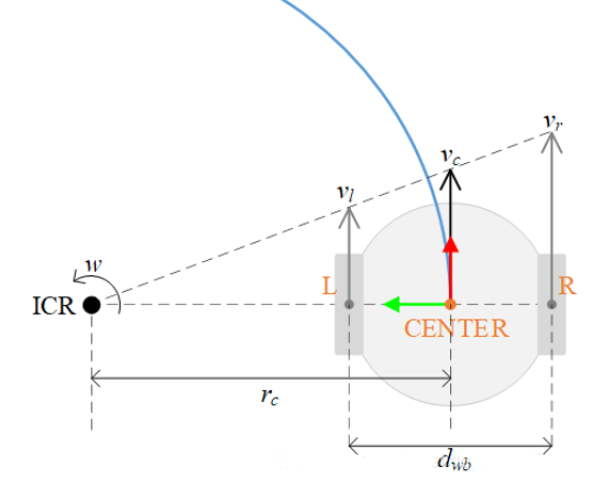
According to the instantaneous kinematics analysis of the vehicle, when the vehicle turns, the left and right wheels move around the same instantaneous center of rotation (ICR) (as shown in the figure)

The angular velocity of the vehicle (the rate of change in heading angle) ![]() .
.
The difference in linear velocity between the left and right wheels is generated by the rotation of the vehicle around the ICR, and the geometric relationship satisfies:
![]() ,
, ![]()
Among them,
B is the distance between the left and right wheels (assuming a fixed value);
R is the turning radius.
Subtracting the two equations yields: ![]()
Therefore, the rate of change in heading angle (angular velocity) is:
![]()
1. Corrections and limitations in practical applications
⚪ Calibration of wheelbase: The actual wheelbase may vary due to load or suspension deformation and needs to be calibrated regularly; The formula assumes that the left and right wheels are symmetrical, and the model needs to be adjusted for asymmetric vehicles.
⚪ Slip and error compensation: During rapid acceleration/braking, the tire slips, causing longitudinal slip and resulting in a wheel speed difference that does not match the true angular velocity. The solution is to introduce IMU angular velocity observations, fuse them through Kalman filtering, or dynamically adjust the slip rate compensation coefficient.
⚪ Tire radius variation: Changes caused by tire pressure, wear, or load variations require indirect calibration through external sensors (such as vision/LiDAR).
2. Example explanation
Assuming the parameters of a certain vehicle are as follows:
Track width B=1.5m, tire radius r=0.3m
Left wheel speed: ![]() , Right wheel speed:
, Right wheel speed: ![]()
Calculate the rate of change in heading angle:
![]()
The vehicle turns left at an angular velocity of 0.4 radians per second.
3. Collaboration with other sensors
⚪ Integration with Inertial Navigation System (INS): The wheel speed sensor provides low-frequency but drift free angular velocity observations, which can correct the accumulated errors of the INS gyroscope.
⚪ Integration with GPS/vision: Long term absolute heading calibration to suppress deviations caused by slip or model errors in the wheel speed sensors.
4. Conclusion
The formula for calculating the rate of change of heading angle through wheel speed difference using a wheel speed sensor is: ![]()
Its advantage lies in strong real-time performance and no cumulative error, but it is limited by slip, tire parameter changes, etc. In practical systems, multi-sensor fusion (such as INS, GPS) is needed to improve robustness.

Xml política de Privacidade blog Mapa do site
Direitos autorais
@ Micro-Magic Inc. Todos os direitos reservados.
 SUPORTADO POR REDE
