
The core mission of an optoelectronic pod is to isolate the optical payload from the angular and linear motion disturbances of the host platform, ensuring that the Line of Sight (LOS) remains highly stable within inertial space, while also enabling the geolocalization of targets. This solution employs an overall architecture based on a "MEMS Inertial Measurement Unit (IMU) mounted on the stabilized platform + multi-source information fusion."
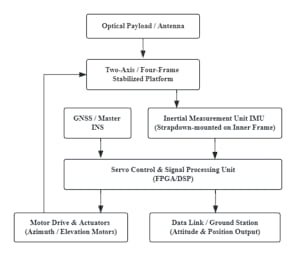
As illustrated in Figure 1, the system architecture comprises an inertial measurement module (three-axis gyroscope and accelerometer), a GNSS receiver, a servo control and drive module (FPGA/DSP), and a two-axis or four-gimbal stabilization platform.
The system employs an IMU, mounted in a follow-motion configuration, to directly sense the angular motion of the line-of-sight (LOS). Through strapdown inertial navigation algorithms, the attitude matrix is updated, enabling the real-time calculation of the LOS attitude angles—namely, heading (yaw) angle "ψ", pitch angle "θ", and roll angle "γ"—relative to a navigation reference frame (such as the North-East-Down or North-East-Up coordinate system).
The differential equation for attitude updates is formulated using the quaternion method to avoid the issue of gimbal lock.

The core of LOS stabilization lies in isolating the system from carrier disturbances through a closed-loop rate control scheme. The control law employs a classic three-loop nested architecture: a current loop (inner loop), a velocity loop (stabilization loop), and a position loop (tracking loop).
To address LOS drift caused by the Earth's rotation, a feedforward compensation algorithm is required. Based on the aircraft's latitude, heading, and attitude, the component of the Earth's angular velocity projected onto the pod's pitch axis—denoted as ωie, p—is calculated and fed forward to the velocity loop's setpoint to counteract the drift.

To compensate for the cumulative errors of MEMS inertial sensors, an adaptive Extended Kalman Filter (EKF) is employed to fuse GNSS position/velocity information with IMU measurement data. The state vector "X" includes position errors, velocity errors, attitude errors, and the biases of the gyroscopes and accelerometers.

This system establishes clear quantitative targets for core performance metrics and applies the principle of error allocation to constrain individual components.
Attitude Accuracy: Better than 0.05° (RMS) for roll and pitch axes, and better than 0.1° (RMS) for heading. These are achieved through dual-antenna GNSS/primary inertial navigation system (INS) transfer alignment, supplemented by magnetic sensors or GNSS-based heading determination.
Line-of-Sight (LOS) Stabilization Accuracy: Better than 50 μrad, ensured by a frequency-decomposition-based variable-gain control algorithm designed to isolate the system from platform vibrations and maneuvering disturbances.
Data Update Rate: No less than 400 Hz, meeting the real-time control requirements of high-speed servo loops.
Drift Suppression: Drift is limited to no more than 0.4° over a 30-minute period, achieved via feed-forward compensation for Earth’s rotation and online estimation of inertial sensor biases using an adaptive Kalman filter.
Error Allocation: For LOS stabilization errors, mechanical resonance accounts for 50%, gyroscope noise for 30%, and control lag for 20%. For attitude errors, gyroscope drift accounts for 60%, accelerometer noise for 25%, and auxiliary sensor accuracy for 15%. The combined RMS value of these errors meets the overall system specifications.
By deeply integrating a slave MEMS-IMU, a three-loop cascaded control architecture, and an adaptive Kalman filter, this solution achieves an LOS stabilization accuracy of better than 50 μrad, satisfying the high-dynamic application requirements of typical airborne optoelectronic platforms. Future work will focus on further optimizing heading retention in GNSS-denied environments and enhancing full-attitude performance during high-dynamic maneuvers.
Deixe um recado
Escaneie para o WeChat :