If the communication between the sensor module and the user system is carried out using UART, SPI or IO methods, generally, the interface voltage level of the sensor module is 3.3V, and the voltage level of the user system is also 3.3V. Usually, a direct connection method is feasible. However, if the interface voltage level of the user system is 1.8V or 5V, when the module interacts with the single-chip microcomputer system for data exchange, due to the mismatch of the voltage levels of the two communicating parties, it may lead to communication failure, current backflow, abnormal power consumption, voltage abnormality and other problems. This article will introduce several common level matching methods, and users can choose specifically according to the actual situation.
Supply the two required conversion power supplies to the two sides of the conversion chip, and then connect the required input and output signals of the conversion to the input and output of the chip. All conversion parts are completed by the chip internally. The following figure shows the level conversion circuit using SN74LVC2T45DCTR.

The advantages of this scheme are that it is very fast, has strong driving capability, and is easy to use. The disadvantages are that the cost is relatively high.
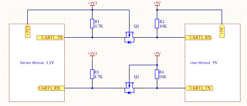
As shown in the figure below, this is a bidirectional level conversion circuit.
First, let's analyze the situation where data is sent from 3.3V to 5V. When the UART1_TX terminal is at a high voltage, the MOSFET Q1 is in the cut-off state, and the UART2_RX terminal is pulled up to its power supply voltage. When the UART1_TX terminal is at a low voltage, the MOSFET Q1 conducts, and the UART2_RX terminal is pulled down to a low voltage level by Q1, completing the level conversion.
Second, let's analyze the situation where data is sent from 5V to 3.3V. When the UART2_TX terminal is at a high voltage, both the MOSFET Q2 and the body diode are in the cut-off state, and the UART1_RX is pulled up to a high voltage by R3. When the UART2_TX outputs a low voltage, the MOSFET does not conduct, but the body diode of the MOSFET pulls the UART1_RX down to a low voltage level. At this point, Vgs is greater than the turn-on voltage, and the MOSFET conducts, further lowering the voltage of UART1_RX.
MOSFETs can also be replaced with transistors.

The advantage of this solution is its low cost, while the disadvantage is that the baud rate of the data generally cannot exceed 400 kbps.
This solution only uses one type of component - resistors, as shown in the figure below. When the 3.3V level module sends data to the right, it only passes through the current-limiting resistor, and the level at the receiving end of the client is within the range. When the 5V level client sends data to the left, it uses two resistors for voltage division, and the voltage at the receiving end on the left is 5V * 2K / (1K + 2K) ≈ 3.3V.

The advantage of this solution is that it has extremely low cost and is convenient for PCB board layout. The disadvantage is that it has weak driving capability and cannot achieve very high speed. Generally, the baud rate applied in this way does not exceed 100 kbps.

Xml política de Privacidade blog Mapa do site
Direitos autorais
@ Micro-Magic Inc. Todos os direitos reservados.
 SUPORTADO POR REDE
