Sensores e instrumentos possuem uma faixa de tensão de operação, e somente dentro dessa faixa o sistema pode operar de forma estável e confiável. Sabemos que o limite de alta tensão pode ser controlado por um circuito de proteção contra sobretensão, mas como o limite de baixa tensão é definido? As fontes de alimentação normalmente utilizam uma solução do tipo buck (BUCK) com circuito de baixa queda de tensão (LDO). A tensão mínima de operação é estabelecida pela função UVLO (bloqueio por subtensão) do circuito buck, que atua como um "portão de segurança". Isso garante que o sistema opere somente quando a tensão de entrada estiver acima da tensão UVLO, evitando instabilidades nas fontes de alimentação subsequentes e possíveis interrupções do sistema devido a tensões de entrada excessivamente baixas.
O bloqueio por subtensão (UVLO) é um mecanismo de proteção de circuito que monitora a tensão de entrada do sistema. Quando a tensão de entrada cai abaixo de um limite predefinido, o UVLO desliga a saída da fonte de alimentação, evitando instabilidade do sistema, danos aos componentes e até mesmo riscos à segurança causados por tensão insuficiente.
Design de Limiar Duplo UVLO
Limiar de partida (V_START): Quando a tensão de entrada atinge esse valor, o circuito começa a operar (por exemplo, 6,5 V).
Limiar de desligamento (V_STOP): Quando a tensão de entrada cai para este valor, o circuito para de funcionar (por exemplo, 5V). Tensão de histerese (HYS): Isso evita a comutação frequente causada por flutuações de tensão próximas ao limiar (por exemplo, após iniciar em 6,5V, a tensão deve cair para 5V antes de desligar).
Tomemos como exemplo o circuito integrado de alimentação buck TPS54561 da TI. Sua função UVLO é implementada através do pino EN. Sua estrutura interna inclui dois módulos principais: ① Comparador de tensão: Este módulo detecta a tensão no pino EN em relação a um limite interno (valor típico V_ENA = 1,2 V). ② Fonte de corrente de histerese: Esta fonte fornece uma corrente de histerese de Ihys = 3,4 μA para evitar comutação frequente causada por flutuações de tensão.
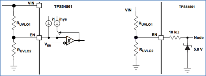
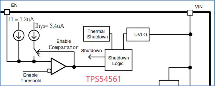
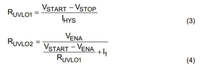
De acordo com a folha de dados, o pino EN do TPS54561 inclui uma fonte de corrente pull-up I1 = 1,2 μA, uma fonte de corrente de histerese Ihys = 3,4 μA e V_ENA = 1,2 V (limiar do pino EN). O limiar UVLO é configurado usando dois resistores divisores de tensão, conforme mostrado na fórmula a seguir:
Método de configuração UVLO TPS54561
Utilize uma rede divisora de resistores externa para ajustar a tensão de partida (V_START) e a tensão de desligamento (V_STOP) do UVLO:
Inicie quando a tensão de entrada for ≥ 6,5V (adicione incrementos de 1 a 3V à tensão de saída alvo de 5V, neste caso 5V + 1,5V = 6,5V).
Pare quando a tensão de entrada for ≤ 5V (porque a tensão de saída alvo é 5V).
Etapas de cálculo:
Calcule R1/R_UVLO1:
R_UVLO1 = (V_START - V_STOP) / I_HYS = (6,5V - 5V) / 3,4μA ≈ 442kΩ
Calcule R2/R_UVLO2:
R_UVLO2 = (V_ENA * R_UVLO1) / (V_START - V_ENA + I1 * R_UVLO1) ≈ 90,9kΩ
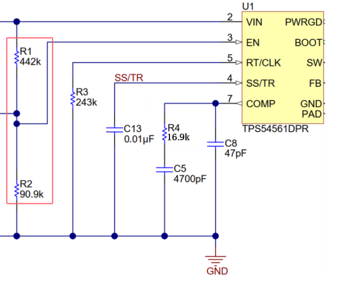
O resultado final é mostrado na figura abaixo:
O UVLO funciona como um cão de guarda para o sistema de alimentação, tomando medidas decisivas quando a tensão está anormal, adicionando uma camada de segurança à sua solução de alimentação!

Xml política de Privacidade blog Mapa do site
Direitos autorais @ Micro-Magic Inc Todos os direitos reservados.
 REDE SUPORTADA


 Português